Fly By Wire systems (FBW)
.
What is a Fly-by-Wire (FbW) system ?
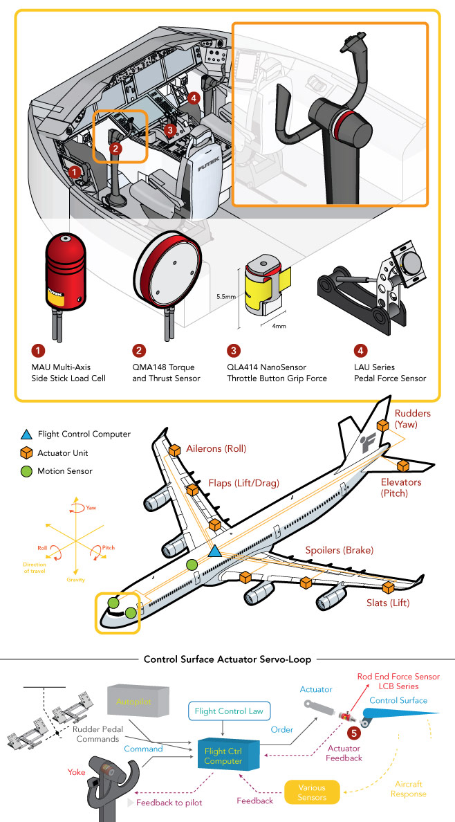
The Fly-by-Wire system is an automated flight control system that processes commands entered by the pilot or autopilot and sends the corresponding commands to the flight control actuators. This automated electronic device replaces the traditional mechanical and hydraulic flight control systems (levers, rods, cables and pulleys) allowing the pilot to remotely control the control surfaces.
The aircraft's flight control computer (FCC) monitors sensors throughout the aircraft to make automatic adjustments in the flight control surface actuators to improve flight safety and performance, based on flight control laws. The FbW is essentially a closed-loop automated control system and its basic elements are as follows :
- The reference input provided by the autopilot or pilot through the control column, side stick, pedals, or any other actuator ;
- The flight control computer (FCC), which calculates how much the aircraft's current aerodynamic variables deviate from the reference input and what action must be commanded to the actuators to safely maneuver the aircraft according to flight control laws;
- Surface control actuators, which translate the FCC signal command into hydromechanical force/torque to change the position/angle of the surface controls (rudder, elevators, slats, spoilers, flaps and ailerons). They are directly responsible for modifying the aircraft's main axis of rotation (roll, pitch and yaw);
- Aircraft instruments or sensors, which provide response feedback to the FCC for comparison to the reference input and estimate.
.
How are force sensors used in FBW systems ?
Multi-axis force and torque sensors are used very frequently in the flight test environment to validate the control system design based on flight control laws. Load cells and multi-axis sensors are added to the control system during the verification and validation phase to verify and calibrate the parameters of the fly-by-wire control loops. Flight controls must be validated during the product design phase and require extreme verification before flight use.
.
How does it work ?
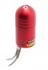
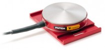
- Side Stick : During the product validation phase, the MAU300 shift load cell provides quality assurance and flight control engineers with the proper tools to measure the force applied to the side stick flight controls. To ensure this mechanism is working properly, the FUTEK MAU300 Multi-Axis Gear Shift Load Cell can be installed in the shaft of each lateral flight control stick.
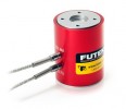
- Stick : Pilots rely heavily on the stick to guide the pitch and roll of an aircraft. By rotating the stick, the pilot maneuvers along the roll axis. By moving the stick forward and backward, the pilot can adjust the elevation and pitch axis. To ensure that the control column is functioning properly, quality assurance and flight control engineers can install the FUTEK MBA500 biaxial torque and thrust sensor to measure the forces and torques applied to the control column flight control. The MBA500 multi-axis force transducer measures in the Mz (roll) and Fz (pitch) axes.
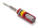
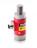
- Throttle grip : The QLA414 nano-sensor or the LMD300 pinch force sensor can be used in the throttle actuation buttons to measure the pinch or pressure force exerted by the pilot.
- Pedals : The pedals control the rudder control surface, which can move left and right by pushing the corresponding rudder pedal. The use of LAU220 pedal force sensors allows engineers to verify the accuracy of these controls. Using FUTEK's LAU pedal force sensors, QA engineers can measure the force required to operate each rudder flight control.
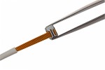
- Surface Control Actuator : During product design validation, the control engineer must measure the actuation force applied to the control surface. This ensures that the required force is applied and that the control loop is properly calibrated and will function as intended. The LCB rod sensor is installed between the actuator and the flight control surface to measure the actual actuation force being exerted and properly calibrate the actuator servo loop with additional force feedback.
.
.
Products Used :
- MAU300 Shift Load Cell ;
- MBA500 Biaxial torque and thrust sensor ;
- QLA414 nanosensor ;
- LMD300 pinch force sensor ;
- LAU220 pedal force transducer;
- LCB400 rod end force sensor;
All these sensors can be combined with the USB220 digital amplifier.
.