Prosthetic Hip Fatigue Testing
.
Hip replacements, like most prostheses, are not one size fits all. Advances in 3D printing technologies such as direct laser metal sintering (DLMS) have made it possible to manufacture customized metal implants at lower cost.
Reliability, durability and fatigue strength are critical to the survival of the implant in a patient. Fatigue and strength testing are required to comply with ISO 7206-4, 6 and PI-58 (ISO 7206-8) and the ASTM F 2580 test specification for hip implants. By integrating load cells with amplifiers with digital and analog signal output capabilities, testing can be easily automated and recorded for compliance purposes.
.
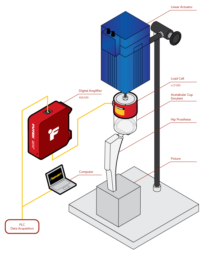
How it works :
- The femoral stem of the prosthetic hip joint is secured in a test device. The femoral head is then attached to a suitable cup.
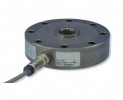
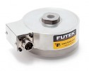
- An LCF300 series load cell is then mounted between the acetabulum and a linear actuator to apply a force during the test.
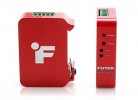
- During the test, the signal from the LCF300 sensor is sent to the IDA100 amplifier. The IDA100 generates an amplified analog signal that can be sent back to a control test machine.
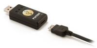
- The digital signal from the IDA100 is transmitted via USB to the FUTEK SENSIT software for displaying/recording/plotting data in accordance with ISO 7206-4, 6, and PI-58 (ISO 7206-8), and ASTM F 2580.
- The IDA100 can be digitally configured, allowing sensor calibration, gain and zero adjustment from a PC running SENSIT.
- The LCF300 is one of the least sensitive transducers to transverse forces.
- In addition, the FUTEK MTA500 multi-axis force transducer can be used to measure forces along the Z-axis and moments around the X- and Y-axis.
.
Related products
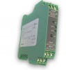
SM18-GAGE : Strain Gage Signal Conditioning Amplifier with Voltage and Current Output
IHH500: Intelligent Digital Hand Held Display (USB output)

SENSIT: FUTEK Test and Measurement Software

IPM650: Intelligent Panel Mount - USB Output

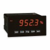
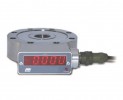
PAXS : Digital display for strain gage sensors
FUTEK USB220: External High Resolution/Speed USB Output Kit
LCF450 -- LCF550 : Tension Compression Pancake Load Cell +/- 250 Lb .... +/- 400 000 Lb
SM5813 : Tension and Compression Pancake Load Cell +/- 3 ... +/- 3000 KN
SM4-DIGITAL : Tension and Compression Pancake with integrated digital display
SM4: Tension and Compression Pancake Load Cell - Up to 500T

LCF400: Tension Compression Pancake Load Cell +/-250 Lb to +/-5000Lb
LCF451 -- LCF551: Fatigue Rated Low Profile Universal Pancake Load Cell

FUTEK USB320: External USB Kit (Amplified Input)
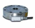
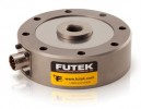
LCF300 : Tension Compression Universal Load Cell - From +/- 25 Lb to 500 Lb
IAA100 : Strain Gage Signal Conditioning Amplifier with Voltage Output
SM4-AMP: Tension and Compression Pancake Load Cell - Up to 500T